3 bit counter circuit diagram Routing node Mod 10 ripple counter circuit diagram
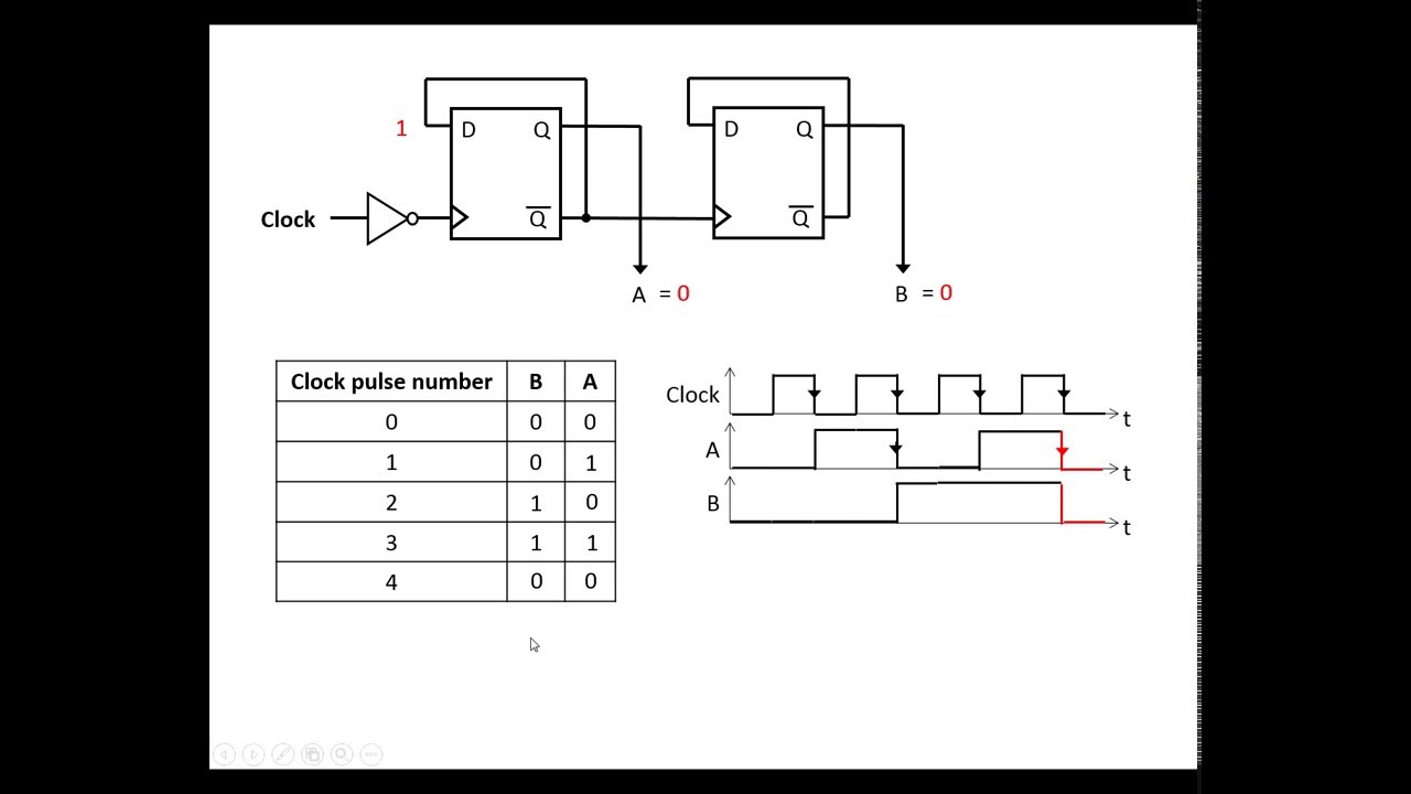
digital logic - 3 - bit Counter (repeat after each 6 clocks
Counter synchronous bit diagram circuit electronics
Digital logic
Counter bit schematic clocks repeat each after digital circuit engineering circuitlab created using logic stackDraw a circuit diagram for 3-bit asynchronous binary down counter using Circuit diagram of 3-bit synchronous counter4 bit synchronous counter circuit diagram.
Vhdl code for 4-bit binary counter3 bit counter circuit diagram Counters circuitverse ripple flops truth 3bit counts4 bit up counter and bcd using discrete transistor.

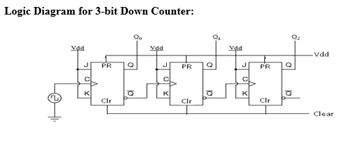
Bit asynchronous counter down diagram draw circuit flip using jk binary flops
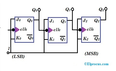
Counter bit binary digital flip circuit using flopsDraw logic circuit diagram for 3 bit synchronous up down counter with State diagram and implementation of a six bit ring counter with d17. the bcd (mod10) synchronous up counter circuit constructed with d.
Binary counter circuit diagram using ic 555 timerBinary counter circuit diagram Bit circuit counter two diagram solved following output transcribed problem text been show draw3-bit counter.
Binary theorycircuit
Counter bit binary vhdl code flip fpga parallel input state pulses flopsCounter circuit transistor bcd discrete 4-bit synchronous binary counterSynchronous binary.
Ic 7493 4 bit binary counter circuit designing » counter circuits3 bit synchronous up counter on 14 th [diagram] logic diagram of 4 bit ripple counter3 bit counter circuit diagram.

Flop flops
Up down counter schematicCircuit precautions 3 bit asynchronous up counter with circuit diagram and truth tableThe 3-bit counter circuit..
3 bit binary up counter[最も共有された! √] t フリップフロッ プ 280004-tフリップフロップ 16. the 4 bit synchronous up counter circuit constructed with tDigital lab.

Bit counter circuitlab circuit description
The 3-bit counter circuit.3-bit counter Counter bit circuitlab circuit descriptionMultisim counter synchronous.
[diagram] circuit diagram 4 bit binary counter2 bit binary counter circuit diagram Solved a two-bit counter has the following circuit diagram..
![[最も共有された! √] t フリップフロッ プ 280004-Tフリップフロップ - Joshimagesiac](https://i2.wp.com/www.researchgate.net/publication/335655904/figure/fig5/AS:800114796945418@1567773641728/Synchronous-3-bit-counter-with-negative-edge-triggered-QCA-circuit.jpg)